Manual Transfer Switch 100 Amp: A Comprehensive Guide
A 100 amp manual transfer switch offers a safe way to connect a generator to your home’s electrical system. It prevents backfeeding‚ which can be dangerous for utility workers.
What is a Manual Transfer Switch?
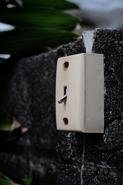
A manual transfer switch (MTS) is an electrical device that allows you to safely switch between two power sources: your utility power and a backup power source‚ such as a generator. Unlike automatic transfer switches‚ an MTS requires manual operation to switch between power sources. This is typically done by flipping a switch or moving a lever.
The primary function of a manual transfer switch is to prevent backfeeding‚ which occurs when power from the generator flows back into the utility grid. Backfeeding can be dangerous for utility workers who may be working on the lines‚ as well as damage electrical equipment. A manual transfer switch ensures that only one power source is connected to your home’s electrical system at any given time‚ providing a safe and reliable way to use a generator during a power outage.
Understanding the Basics of a 100 Amp Manual Transfer Switch
A 100 amp manual transfer switch is designed to handle up to 100 amps of current. It allows switching between utility power and generator power safely and manually.

Purpose of a Manual Transfer Switch
The primary purpose of a manual transfer switch is to safely and effectively switch between two power sources: the utility grid and a backup generator. This ensures uninterrupted power supply during outages. It also prevents backfeeding‚ a dangerous situation where generator power flows back into the utility grid. Backfeeding can harm utility workers and damage equipment.
Manual transfer switches are crucial for maintaining essential services during power interruptions. By isolating the home’s electrical system from the grid‚ the generator can safely power selected circuits. This allows homeowners to run critical appliances like refrigerators‚ heaters‚ and medical equipment. They offer a reliable and cost-effective solution for managing power during emergencies.
Furthermore‚ manual transfer switches provide a controlled and secure method for connecting a generator. This eliminates the need for extension cords‚ which can be a fire hazard and inconvenient to manage. They are a vital component for any home or business seeking to maintain power during outages.
100 Amp Rating Significance
The 100 amp rating of a manual transfer switch indicates its maximum current-carrying capacity. This means the switch can safely handle up to 100 amps of electrical current. This rating is crucial for determining its suitability for a specific application. Selecting the correct amperage ensures safe and reliable operation of the connected electrical system.
A 100 amp transfer switch is typically suitable for homes or small businesses with moderate power requirements. It can accommodate multiple essential appliances and lighting circuits during a power outage. However‚ it’s essential to calculate the total amperage of the circuits you intend to power. Exceeding the 100 amp rating can overload the switch and cause it to fail‚ potentially leading to a fire hazard.
Therefore‚ understanding the 100 amp rating and carefully calculating your power needs is crucial. This ensures the transfer switch can adequately handle the load. Consulting with an electrician is recommended to determine the appropriate size for your specific electrical system.
Installation of a 100 Amp Manual Transfer Switch
Installing a 100 amp manual transfer switch requires careful planning and adherence to safety guidelines. It involves wiring to the main panel and connecting to a generator for backup power.
Safety Precautions Before Installation
Prior to installing a 100 amp manual transfer switch‚ safety is paramount. Always disconnect power from the main electrical panel to prevent electrical shock. Double-check that the circuit breaker is off before proceeding with any wiring. Use insulated tools to further minimize risk.
Verify the absence of voltage with a reliable tester. Consult a qualified electrician if you are not comfortable working with electrical systems. Read and understand the installation manual thoroughly before starting. Ensure adequate electrical clearance is maintained‚ especially around live metal parts.
Wear appropriate personal protective equipment (PPE)‚ including safety glasses and gloves. Never work alone; have someone nearby in case of an emergency. Familiarize yourself with local electrical codes and regulations. Following these precautions will help ensure a safe installation process. Remember‚ safety first!
Tools and Materials Required
Installing a 100 amp manual transfer switch necessitates specific tools and materials. Essential tools include a screwdriver set (both flathead and Phillips)‚ wire strippers‚ a voltage tester‚ and a torque screwdriver. A drill with various drill bits may also be needed for mounting the switch.
Materials required are appropriately sized wires (refer to wire size recommendations)‚ wire connectors‚ electrical tape‚ and the manual transfer switch itself. Ensure you have the correct breakers for your panel. Consider using a level to ensure proper alignment during installation.
Additionally‚ gather safety glasses‚ gloves‚ and a flashlight. Having a copy of the wiring diagram and the installation manual readily available is crucial. Finally‚ check local electrical codes for any additional required materials. Proper preparation ensures a smooth and safe installation. Don’t forget to label everything clearly!
Step-by-Step Installation Guide
Step 1: Prioritize safety! Disconnect power to the main panel. Step 2: Mount the transfer switch near the main panel‚ ensuring proper electrical clearance. Step 3: Connect the generator inlet box to the transfer switch‚ routing wires carefully.
Step 4: Wire the transfer switch to the main panel‚ following the wiring diagram precisely. Use appropriately sized wires and secure connections. Step 5: Install breakers in the main panel for the transfer switch circuits.
Step 6: Connect essential circuits to the transfer switch. Step 7: Double-check all wiring connections for accuracy and tightness. Step 8: Restore power to the main panel.
Step 9: Test the transfer switch with a generator‚ ensuring proper operation. Step 10: Label all circuits clearly. Consult a qualified electrician if unsure about any step. Remember to follow local electrical codes throughout the entire process. A successful installation guarantees a seamless power transition.
Wiring to the Main Panel
Connecting the 100 amp manual transfer switch to the main electrical panel requires careful attention to detail and strict adherence to safety protocols. Begin by identifying a suitable location within the main panel for the new circuit breakers that will feed the transfer switch.
Typically‚ a double-pole 100 amp breaker is required. Ensure the breaker is compatible with your panel. Turn off the main breaker before working inside the panel.
Next‚ run appropriately sized wires (typically 4 AWG copper or 2 AWG aluminum‚ but consult local codes) from the transfer switch to the corresponding breaker locations in the main panel. Connect the wires to the breakers‚ ensuring a tight and secure connection.
Connect the neutral and ground wires to the appropriate bus bars within the main panel. Double-check all connections for tightness and proper polarity. Once completed‚ carefully re-install the panel cover and restore power. Professional installation is highly recommended.
Wiring Diagrams and Schematics
Understanding wiring diagrams and schematics is crucial for a safe and correct installation of a 100 amp manual transfer switch. These diagrams provide a visual representation of the electrical connections between the transfer switch‚ the main electrical panel‚ and the generator. Look for diagrams specific to your transfer switch model‚ as wiring configurations can vary.
A typical schematic will illustrate the line (hot)‚ neutral‚ and ground connections‚ showing how the transfer switch isolates the chosen circuits from either the utility power or the generator. Pay close attention to the color coding of wires‚ as specified in the diagram‚ to ensure correct connections.
Wiring diagrams often include details such as wire gauges‚ conduit fill requirements‚ and the placement of grounding electrodes. Always consult the manufacturer’s documentation for the most accurate and up-to-date wiring information. If you’re not comfortable interpreting these diagrams‚ seek assistance from a qualified electrician.
Wire Size Recommendations
Selecting the correct wire size for a 100 amp manual transfer switch is paramount for safety and optimal performance. Undersized wires can overheat‚ leading to insulation damage‚ fire hazards‚ and voltage drop‚ which can harm appliances. The National Electrical Code (NEC) provides guidelines for wire sizing based on ampacity and conductor material.
For a 100 amp circuit‚ copper conductors typically require a minimum of #3 AWG (American Wire Gauge). Aluminum conductors‚ which have lower conductivity‚ will need a larger gauge‚ usually #1 AWG. These are general recommendations and can vary based on the specific installation conditions‚ such as ambient temperature and the number of current-carrying conductors in a conduit.
Furthermore‚ consider the length of the wire run. Longer runs require larger wire sizes to minimize voltage drop. Consult the NEC voltage drop tables or use online calculators to determine the appropriate wire size for your specific installation. Always prioritize safety and adhere to local electrical codes.
Testing the Installation
After installing a 100 amp manual transfer switch‚ thorough testing is crucial to ensure safety and proper functionality. Begin by visually inspecting all wiring connections for tightness and correct polarity. Use a multimeter to verify that the voltage at the transfer switch input and output terminals matches the expected values for both utility and generator power.
Next‚ with the utility power on‚ switch the transfer switch to the generator position. The power should remain off to the generator-fed circuits. Start the generator and allow it to stabilize. Then‚ switch the transfer switch to the generator position. The generator should now power the selected circuits.
Check the voltage and amperage at several points in the generator-powered circuits to ensure they are within acceptable ranges. Finally‚ switch back to utility power and verify that the generator shuts down or disconnects properly. If any issues arise‚ immediately disconnect power and troubleshoot the wiring.

Applications of a 100 Amp Manual Transfer Switch
A 100 amp manual transfer switch is ideal for providing backup power to homes or small businesses during outages. It allows safe switching between utility and generator power.
Generator Integration
Integrating a generator with a 100 amp manual transfer switch involves several key considerations for safety and functionality. The primary goal is to allow seamless switching between utility power and generator power during an outage. This setup prevents backfeeding‚ protecting utility workers and your home’s electrical system. The generator’s capacity must align with the transfer switch’s rating to avoid overloading.
Proper wiring is crucial; use appropriately sized wires based on the generator’s amperage and distance from the switch. Refer to wiring diagrams for correct connections‚ ensuring compliance with electrical codes. The transfer switch should be easily accessible for manual operation. Regular testing of the generator and transfer switch is recommended to verify performance. A well-integrated system provides reliable backup power.
Dual Power Source Switching
A 100 amp manual transfer switch facilitates switching between two power sources‚ typically utility power and a generator. This allows users to manually select the power source for their home or business. The switch prevents backfeeding‚ ensuring safety for utility workers and protecting electrical equipment.
When switching‚ ensure the generator is running and stable before transferring the load. It’s crucial to avoid overloading the generator by understanding the amperage requirements of connected appliances. Regular inspection and maintenance of the transfer switch are essential for reliable operation. Consider the switch’s compatibility with different generator types and electrical systems. A properly installed and maintained switch provides flexibility and peace of mind during power outages‚ allowing for a smooth transition between power sources.
Residential Use Cases
In residential settings‚ a 100 amp manual transfer switch provides a reliable backup power solution. It allows homeowners to power essential appliances during outages. This includes refrigerators‚ lights‚ and heating or cooling systems. The switch ensures safe generator connection. It prevents dangerous backfeeding onto the utility grid.
Homeowners can select specific circuits to power‚ optimizing generator usage. Consider installing a transfer switch to maintain essential services. It provides comfort and security during emergencies. The 100 amp capacity is suitable for many homes‚ but assess your power needs. Professional installation ensures safety and code compliance. Regular testing verifies proper operation. A manual transfer switch offers peace of mind‚ knowing you can manage power outages effectively and safely. It provides independence from utility disruptions.

Important Considerations
When choosing a 100 amp manual transfer switch‚ consider electrical clearances. Also‚ ensure compatibility with your generator. Finally‚ pay attention to appliance amperages to avoid overloading the system during operation.
Electrical Clearance Requirements
Maintaining proper electrical clearance around a 100 amp manual transfer switch is crucial for safety and code compliance. Ensure that you adhere to the minimum clearance requirements specified by local electrical codes and the manufacturer’s instructions. Adequate space is necessary to prevent accidental contact with live parts and to allow for proper ventilation‚ which helps prevent overheating.
Electrical clearance refers to the unobstructed space required around electrical equipment to provide safe working conditions and prevent electrical hazards. For circuits ranging from 100 to 400 amps‚ a minimum clearance of at least 1/2 inch should be maintained between live metal parts and any grounded metal surfaces. It’s also important to consider vertical and horizontal clearances from other objects‚ such as walls‚ ceilings‚ and other equipment.
Failing to maintain proper electrical clearances can result in electrical shock‚ arc flash‚ and fire hazards. Always consult with a qualified electrician to ensure that your installation meets all applicable safety standards and regulations.
Compatibility with Different Generators
Ensuring compatibility between your 100 amp manual transfer switch and your generator is vital for safe and effective operation. The transfer switch’s amperage and voltage ratings must match or exceed those of the generator. It is also crucial to verify that the transfer switch is designed to work with the specific type of generator you intend to use‚ whether it’s a portable gas generator‚ a solar-powered system‚ or another auxiliary power source.
Different generators may have varying voltage requirements and wiring configurations. Some generators supply 120/240V‚ while others may offer different voltage options. The transfer switch must be compatible with the generator’s output voltage to prevent damage to the switch or connected appliances.
Furthermore‚ consider the generator’s starting wattage and running wattage. Ensure that the transfer switch can handle the surge of power required when the generator initially starts up. Consult the generator’s specifications and the transfer switch’s documentation to confirm compatibility before installation.
Appliance Amperage Considerations
When using a 100 amp manual transfer switch‚ carefully consider the amperage requirements of the appliances you plan to power during an outage. Overloading the transfer switch can lead to tripped breakers‚ damage to equipment‚ or even fire hazards. Begin by creating a list of essential appliances‚ such as refrigerators‚ lights‚ and heating systems.
Determine the amperage draw of each appliance‚ either by checking the appliance’s label or referring to the circuit breaker rating in your load center. Remember that some appliances‚ like air conditioners and refrigerators‚ require a higher starting amperage than their running amperage. Ensure that the total amperage of all connected appliances does not exceed the 100 amp capacity of the transfer switch.
If the total amperage exceeds 100 amps‚ prioritize essential appliances and avoid using non-essential ones during generator operation. Consider using energy-efficient appliances to reduce overall amperage draw. Caution: Reliance transfer switches should not be used for appliances or systems that may exceed the capacity of the product.

Additional Resources
To aid in your understanding and installation‚ consult installation manuals and wiring diagram indexes. These resources offer detailed guidance and specific schematics for various transfer switch configurations and models.
Installation Manuals
Installation manuals are critical resources when working with a 100 amp manual transfer switch. These manuals provide step-by-step instructions tailored to specific models‚ ensuring safe and correct installation. Before commencing any work‚ thoroughly read and understand the manual relevant to your transfer switch unit.
These manuals often include detailed diagrams‚ safety precautions‚ and troubleshooting tips. They highlight the necessary tools‚ wiring specifications‚ and testing procedures. Adhering to the manual’s guidelines is essential to prevent electrical hazards and ensure optimal performance. Failure to follow instructions may void warranties or lead to dangerous situations.
Look for manuals specific to your transfer switch model‚ as wiring and configurations can vary. Always prioritize safety and consult a qualified electrician if you have any doubts or encounter unfamiliar steps during the installation process.
Wiring Diagram Index
A wiring diagram index is a valuable tool when installing or troubleshooting a 100 amp manual transfer switch. This index provides a comprehensive list of wiring diagrams and schematics for various transfer switch configurations. Each diagram illustrates the correct wiring connections for different voltages‚ amperages‚ and generator types.
Using the index‚ you can quickly locate the appropriate wiring diagram for your specific transfer switch model. These diagrams are essential for ensuring that the switch is wired correctly‚ preventing electrical hazards and ensuring proper operation. Pay close attention to wire colors‚ terminal locations‚ and grounding requirements as outlined in the diagrams.
The index may also include diagrams for different installation scenarios‚ such as integrating a generator or switching between dual power sources. By consulting the wiring diagram index‚ you can simplify the installation process and avoid potentially dangerous wiring errors.